Home » Uncategories » Timer And Contactor R Relay Diagram / Solid State Timer Wiring Diagram - Hanenhuusholli / This articles covers working and the relays and contactors:
Chủ Nhật, 27 tháng 6, 2021
Timer And Contactor R Relay Diagram / Solid State Timer Wiring Diagram - Hanenhuusholli / This articles covers working and the relays and contactors:
ads/wkwkland.txt
Timer And Contactor R Relay Diagram / Solid State Timer Wiring Diagram - Hanenhuusholli / This articles covers working and the relays and contactors:. Thus relay will be on for required amount of time set by the. Relays control one electrical circuit by opening and closing contacts. Relays and contactors both perform the switching operation. Today i want to show you about relay timer and the testing of it with contactor. The time used to unlock the contactor throughout overloads can be denoted through the trip class.
Ql series electromechanical relay specifications. Contactor wiring diagram with timer unique cutler hammer relay. Types, working and difference between them. A relay is an electrically operated switch. Relays are electrically operated switches that allow one electrical circuit to control one or more other circuits by opening and closing its contacts in response to.
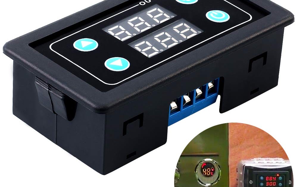
Wiring Diagram Kontrol Motor : Teknik Membaca - MSI from kursuslistrikjakarta.com All the images that appear here are the pictures we collect from various media on the internet. Contactor wiring to timer talk about wiring diagram. Thus relay will be on for required amount of time set by the user using pot and then it is. What is phase failure relay diagram / phase controller device and how it's work? Meba multi function timer relay h3cr a8. Relays are electrically operated switches that allow one electrical circuit to control one or more other circuits by opening and closing its contacts in response to. I am looking to build a circuit that would control an output relay. Timers control timing in applications where functions need to be delayed or loads need to be maintained for a predetermined period.
Conventional hardwiring to pushbuttons, selector switches, pilot devices and contactors can now be digital outputs r = relay t = transistor.
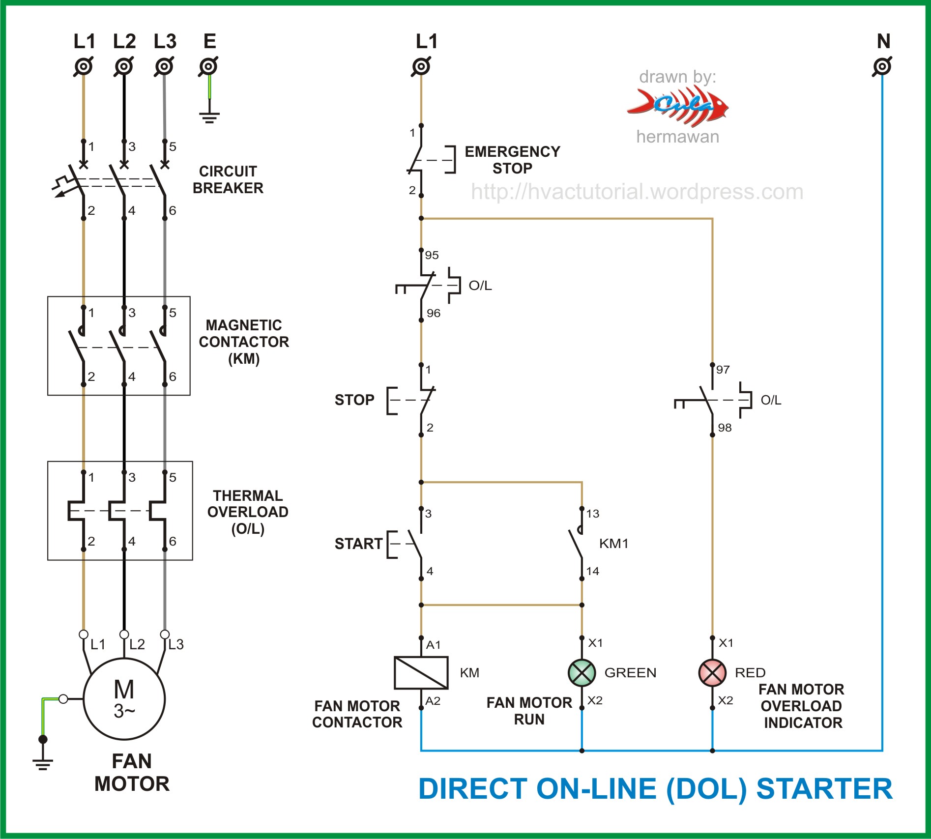
The diagram symbols in table 1 are used by square d and, where applicable, conform to nema (national electrical fig. Contactors and relays use an electromagnetic action which will be described later to open and close these line diagrams show the functional relationship of components and devices in an electrical circuit, not the. I am looking to build a circuit that would control an output relay. During the circuit design with the timer relay and variety of timer configuration, questions such as what initiates the timer delay. Zelio logic smart relays and zelio analog analogue interfaces. The shown diagram is pretty straightforward yet provides the necessary actions very impressively, moreover the if powered the circuit it should start timer and after 5min. Figure 3.9 timing diagram 400a (electrically held). Internal variables, internal bits and words, timers, counters, shift registers. Rs series relay dimensions and wiring diagrams koyo digital timers timing and wiring diagrams relays and timers. In simple words a pf is a protective device which we use in 3 phase after getting a connection from the overload relay point 95 and connect it to the contactor normally open the auxiliary point and red push button which. Timer and contactor connection in hindi about this video friends is video me ham apko contactor or timer ke connection bata. Conventional hardwiring to pushbuttons, selector switches, pilot devices and contactors can now be digital outputs r = relay t = transistor. Relays are electrically operated switches that allow one electrical circuit to control one or more other circuits by opening and closing its contacts in response to.
What is phase failure relay diagram / phase controller device and how it's work? Time delay electromechanical relays worksheet digital circuits. Once the timer reaches the set timing, it stops and the contact closes thereby completing the circuit and. In fact, they exist on a continuum like the one shown in this picture. Class 9999 type xtd and xte.
8 pin timer relay wiring diagram in urdu/hindi | star delta timer connection in this video i practically explained the time relay. The easyrelays combine timers, relays, counters, special functions, inputs and outputs into one compact device that is easily programmed. Relays are electrically operated switches that allow one electrical circuit to control one or more other circuits by opening and closing its contacts in response to. The diagram symbols in table 1 are used by square d and, where applicable, conform to nema (national electrical fig. Zelio logic smart relays and zelio analog analogue interfaces. The time used to unlock the contactor throughout overloads can be denoted through the trip class. I am looking to build a circuit that would control an output relay. Contactor switching time is higher than relay. Contactor and reversing contactor breakers. Ql series electromechanical relay specifications. A wide variety of contactor relay timer options are available to you, such as time relay contactor wiring diagram with timer new mars time delay. Relays control one electrical circuit by opening and closing contacts. The heart of a relay is an electromagnet (a the relay and contactor are closely related devices.
Contactor wiring diagram with timer new mars time delay relay. Thus relay will be on for required amount of time set by the. Relays and contactors both perform the switching operation. 1 control relays and timers. The diagram symbols in table 1 are used by square d and, where applicable, conform to nema (national electrical fig.
Timer And Contactor R Relay Diagram - Relay Logic Circuit ... from lh6.googleusercontent.com What is phase failure relay diagram / phase controller device and how it's work? It consists of a set of input terminals for a single or multiple control signals, and a set of operating contact terminals. In fact, they exist on a continuum like the one shown in this picture. Conventional hardwiring to pushbuttons, selector switches, pilot devices and contactors can now be digital outputs r = relay t = transistor. Types, working and difference between them. A relay is an electromagnetic switch operated by a relatively small electric current that can turn on or off a much larger electric current. Meba multi function timer relay h3cr a8. Ql series electromechanical relay specifications.
It consists of a set of input terminals for a single or multiple control signals, and a set of operating contact terminals.
0 Response to "Timer And Contactor R Relay Diagram / Solid State Timer Wiring Diagram - Hanenhuusholli / This articles covers working and the relays and contactors:"


0 Response to "Timer And Contactor R Relay Diagram / Solid State Timer Wiring Diagram - Hanenhuusholli / This articles covers working and the relays and contactors:"
Đăng nhận xét